Complete Guide to Electronics: all that you need to know to start⚡️
 http://www.edoardosorgentone.it
You are interested in electronics but is it too difficult? Too much math? You don’t know where to start?
In this article I want to introduce you to electronics in a simple but complete way. Here you will learn the basis for analyzing circuit, that is essential if one day you want to build your own circuit.
HOW TO ACHIEVE EXCELLENT KNOWLEDGE OF BASIC ELECTRIC CIRCUIT?
As an engineering student here is the path that I suggest you to follow:
- Learn the basic principles of electronics(described in this article)
- Kirchhoff Laws(click here to start this topic):start solving resistor-only circuit
- Norton and Thevenin(click here to start):simplifies the complex circuits
- AC circuits
- Dynamic components: inductors, capacitors
These are the topic you should know to analyze a basic circuit with the most used components.Once you understand the electrotechnics,the next step is the pure electronic, with logical components, transistors etc…
A KEY ADVICE
My key advice for all the engineering subject is to do a lot of exercises ,don’t be afraid to do mistakes, strive to think about the exercises, starting from the easiest and getting to the most complex. Do practice: buy electronic components, a multimeter, led, resistors, capacitors, inductors, a breadboard and start doing experiments!Have fun!😎
Tutorial Topics:
- Electronic Fundamental Quantities: current, voltage, power
- Elecric Circuits: all you need to know, topology
- Components and other definitions
P.s. if you are not familiar with math, you can skip the mathematical definitions I’ll give!😉
1-Introduction to electrotechnics
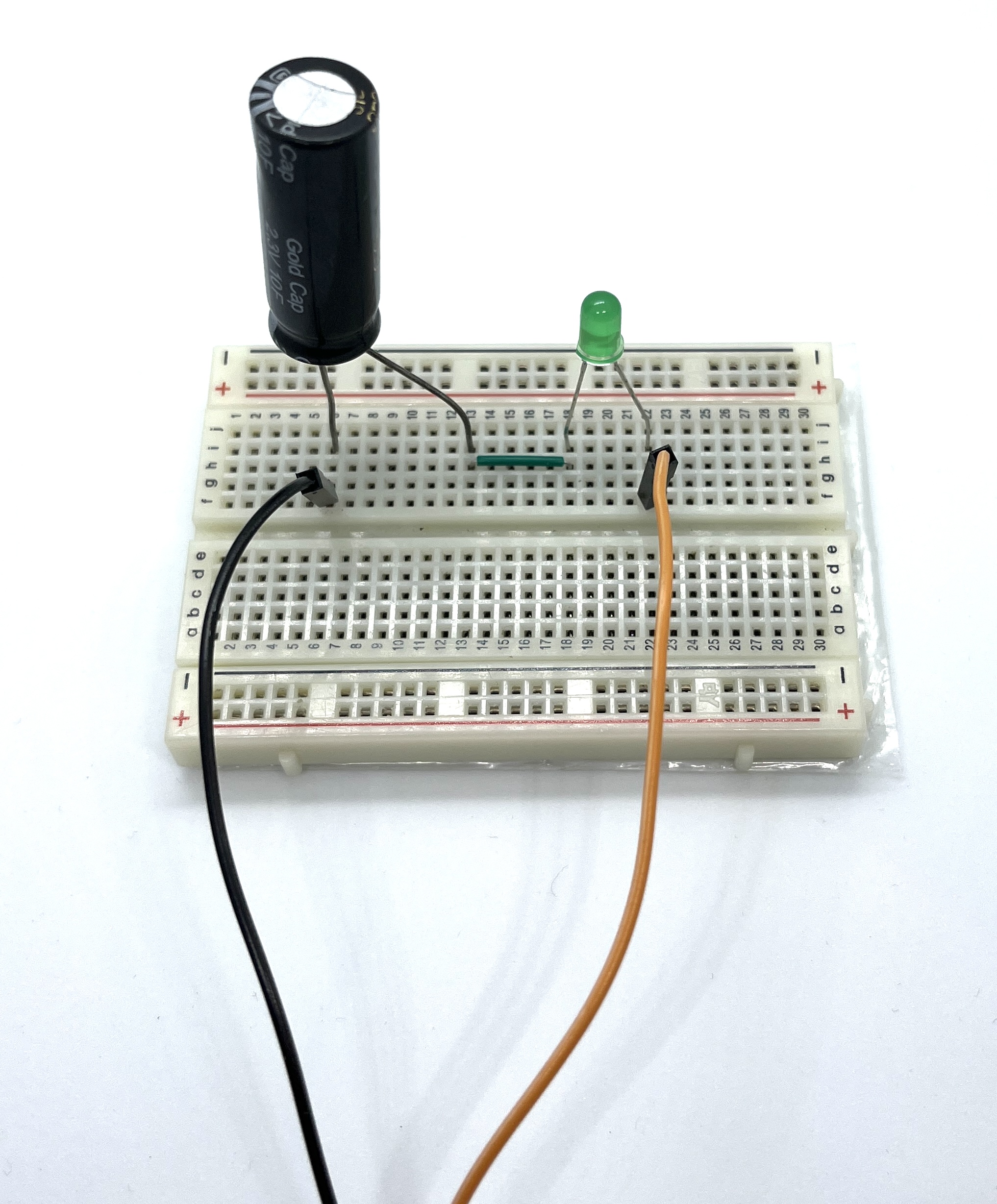
Electrotechnics is the science that analyze electrical circuits in order to understand their behavior: for example, if you consider the following circuit in which there are a LED and a capacitor, you can find out what the LED will do when circuit breaker will be closed.
What will happen? LED will turn on as we connect the circuit to the DC power supply and after X seconds will turn off since the capacitor is charged. This is a trivial example of what can you do with electrotechnics.
WHAT IS ELECTRICITY? WHAT IS IT DUE TO? ⚡️
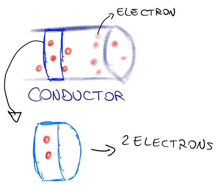
Electricity is a flow of charged particles(electron, with a negative charge), like water flowing in a pipe: current is the measure of how many electric charges pass through the conductor.
Since it is an hard topic,I’m not going to explain detail about the electricity and charges in this article, but I’ll write a specific article for who wants to know why this phenomenon happens and the physical explanation! 🥸
CURRENT 🔌
current is mathematically defined as the time derivative of the charge that passes through a certain area of conductor
In other words, current is the ratio between the amount of charge that flows through an area of conductor and the time that these charges take to pass that area.
Charge is measured in Coulumb(C), time in seconds(s) and current in Ampere(A=C/S).
VOLTAGE ⚠️
Voltage is the measure of how much energy it takes to move a unitary electrical charge (electron) from a position A to another position B.
In a circuit, voltage is measured between 2 points that we will call nodes.
math def:voltage is defined as the charge derivative of the work(for moving a charge from a starting point A to a final point B)
Since work is measured in Joule and charge in Coulumb, voltage is measured in Volt(V=J/C).
Since work is equal to the change of potential energy, voltage can be calculated as
Do not confuse voltage with potential energy: voltage is measured between 2 points, potential is measured in one point.
POWER ⚡️
Electric power is defined as the product of the current and the voltage.
It is measured in Watt:
2-Circuits: topology ,hypotesis, components
Now you will understand how to read a circuit, its connections, its components and conventions used to represent them.
NODES,BRANCHES,LOOPS
A node is a point in the circuit where two or more branches are connected, indicated by a point in a circuit.
In electrical circuits, a branch(or path) is any element or combination of elements that connects two nodes.
A loop is a closed path in a circuit, formed by following a continuous path through branches and nodes without passing through any branch or node more than once. The number of loops in a circuit is equal to the number of independent closed paths.
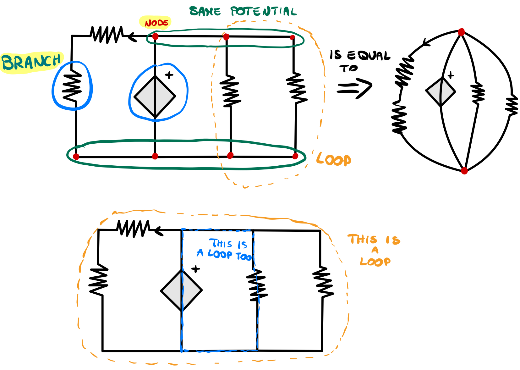
HYPOTESIS
There are some fundamental hypotesis of electrotechnical that make far easier solving a circiut:
- Lumped-element model:it allow us to use Kirchhoff Laws instead of Maxwell’s equations to solve a circuit.This simplifies things a lot!
- Wires have zero resistance(we will see what resistance is)
For the first part of electrotechnical course, we will consider only Direct Current(DC) circuit. We have a direct current when it remain constant over time.Alternate current(AC) changes every X seconds.X depends on the frequency.
For example, in Italy frequency in homes is 50Hz,voltage:230V, so the voltage changes every 0.02 seconds(I will explain this in another article).Here’s the difference in their graph:

I’ll write an article to explain the difference and why in our homes we have AC.Stay updated visiting my website!A free newsletter is coming!Click on the link below to visit my website:
 http://www.edoardosorgentone.it
COMPONENTS
You should start with linear components, so resistance, DC power source…now I want to introduce linear components with symbols:
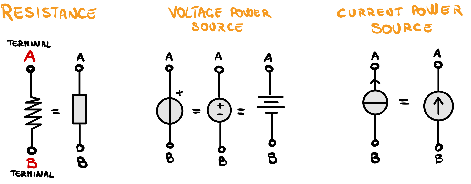
Why these are linear components? Just because their chart is a line and the equation that describes their status(voltage and current) is linear and it does not have derivatives or integrals.
1-RESISTOR
It is the simplest component.Its function is to oppose the passage of current.When this happens, resistor heats up(a little or a lot, it depends on the value of resistance, voltage and current),for example your oven heats up thanks to a resistor that become hot thanks to a principle called Joule effect. The more the resistance, the less current it will pass.
Did you catch that? 😊
To understand what resistance is, consider this analogy:if we take a pipe that at some point becomes narrower, when the water flows inside, on the restriction it will have more pressure and there the tube will heat up since it oppose to the passage of water.
Resistance is measured in Ohm (Ω) and it is the measure of how the resistor oppose to current passage.
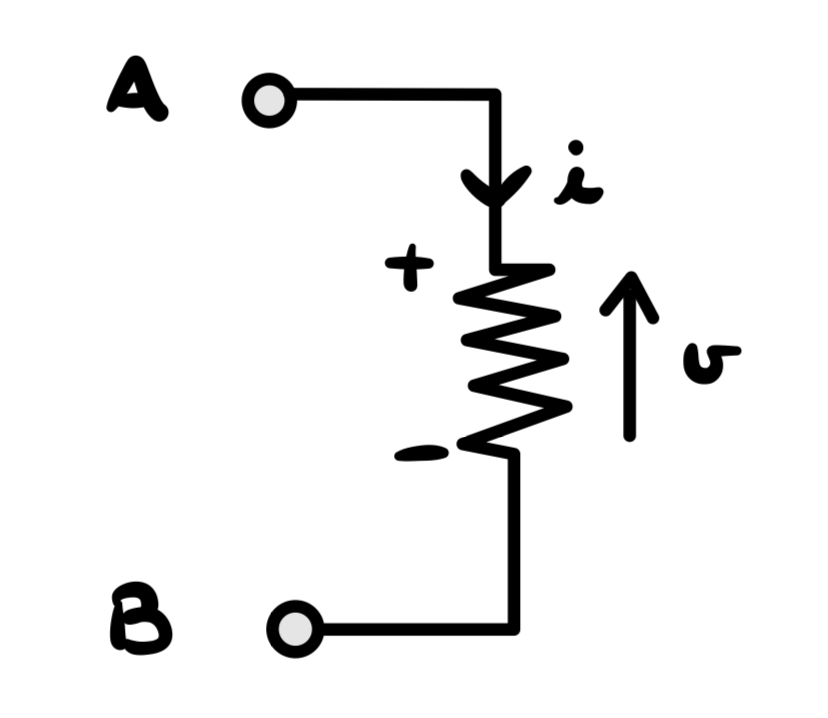
Its voltage-current is described by the First Ohm Law:
where R is the Resistance value,v the voltage between the resistor terminals and i the current that passes through resistor.
In electrical circuits, it is common to use a convention for voltage and current.
The convention for voltage is that it is measured with respect to a reference point/node, called ground, and is positive when moving from ground to the other point. The convention for current is that it flows from the positive terminal of a voltage source to the negative terminal.
Actually there are some people that uses the opposite convention, but the most common is this so I will use this one.
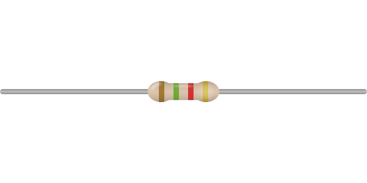
So, in practice, here’s how to determine voltage, current and power in a resistor: first you have to know the value of resistance(in the physical component it is written on it or you calculate it by looking at the color of the stripes,there are sites that allows you to calculate automatically that value).
If you connect a 2 Ω resistor to a 9V battery, the current in the resistor will be 9V/2Ω=4.5A. This because of the First Ohm Law described up here!
Or,if the battery is a current power source(so voltage is unknown) and battery generate 4.5A and the resistance is 2Ω, the voltage will be 4.5A*2Ω=9V.
2-POWER SOURCE
Power source allows electrical charge to move, so a circuit can work thanks to generators.A LED connected to a battery, turns on because the battery gives the energy that is transformed from electrical to light energy and heat (Joule effect of components that we can ignore).
There are 2 types of power source:independent source and controlled source.Let’s start with the independent!
Independent Power Source are really simple: you can have a Voltage Power Source(V.P.S.) and a Current Power Source(C.P.S.),their symbols are shown in the section above.
The difference is this: if you have a V.P.S. you know only the voltage and current is an unknown because it depends on the circuit connected to it.
If you have a C.P.S. you know the current and voltage is an unknown because it depends on the circuit connected to it.Examples:
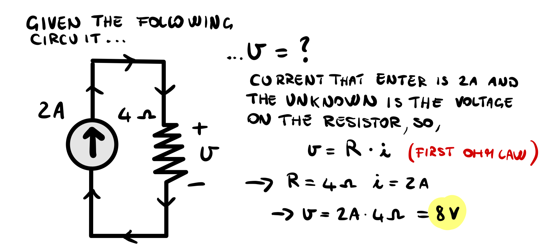
If you buy the classic 9V battery and you build a circuit, the current that the battery will generate is an unknown, so you have to solve the circuit in order to find it.
3-CONTROLLED POWER SOURCE
A controlled power source is a component that amplifies the input signal: for example, consider a current controlled current power source that amplifies by 3 times the input current, if the input is 5A, the output will be 15A.
These kind of component are used for many applications: an example is the microphone, its signal must be amplified before it can be heard in the speakers.
What does it means current controlled or voltage controlled? It’s simple: if a p. source is current controlled, the output will depend on an input that is a current; instead, if it is voltage controlled the output will depend on a voltage given as input.
There are 4 kind of power source:

OTHER IMPORTANT CONCEPTS
- OPEN CIRCUIT: we have a short circuit when resistance tends to infinite(infinitely large) so current will be zero,matematically, for the Ohm Law…
- SHORT CIRCUIT: we have a open circuit when resistane tends to zero so that current will tend to infinity.
The short circuit is most of the time an unwanted situation because wires can heat up so much that they melt for example.
- CONDUCTANCE:it is simply defined as 1/R, where R is resistance.It is measured in Siemens(S).
- Since R and G are always positive, power dissipated by a resistor is always positive.
- BIPOLE: a circuit element that has 2 terminals(a resistor is a bipole, power source,capacitor and inductors too) whose behaviour to external effects is completely defined by the constitutive equation,between voltage and current, for example in a resistor its constitutive equation is i=v/R…📌According to Kirchhoff Laws that we will see in the next article, the current that enter in one bipole terminal must be equal to the current that flows out from the other terminal
- Dynamic components are those components whose voltage and current(these 2 variables are called also signals) depend on time.
Now you know the basic theory concepts required to start doing exercises and understanding electronics.Next time we will see something more practical.
See you at the next tutorial!☺️
